Daha önce burada PIC mikrodenetleyicisi ile LCD‘nin nasıl sürüleceğinden bahsetmiştim. RPi Python kütüphanesi içinde LCD sürmek için bir kütüphane de bulunuyor. Aşağıdaki kod ile komut satırından verebileceğiniz argümanlar ile LCD ekranına değer yazdırabilirsiniz. Kullanımı şöyle olacaktır:
sudo python lcd2.py ‘Merhaba Raspi’ ‘www.tankado.com’
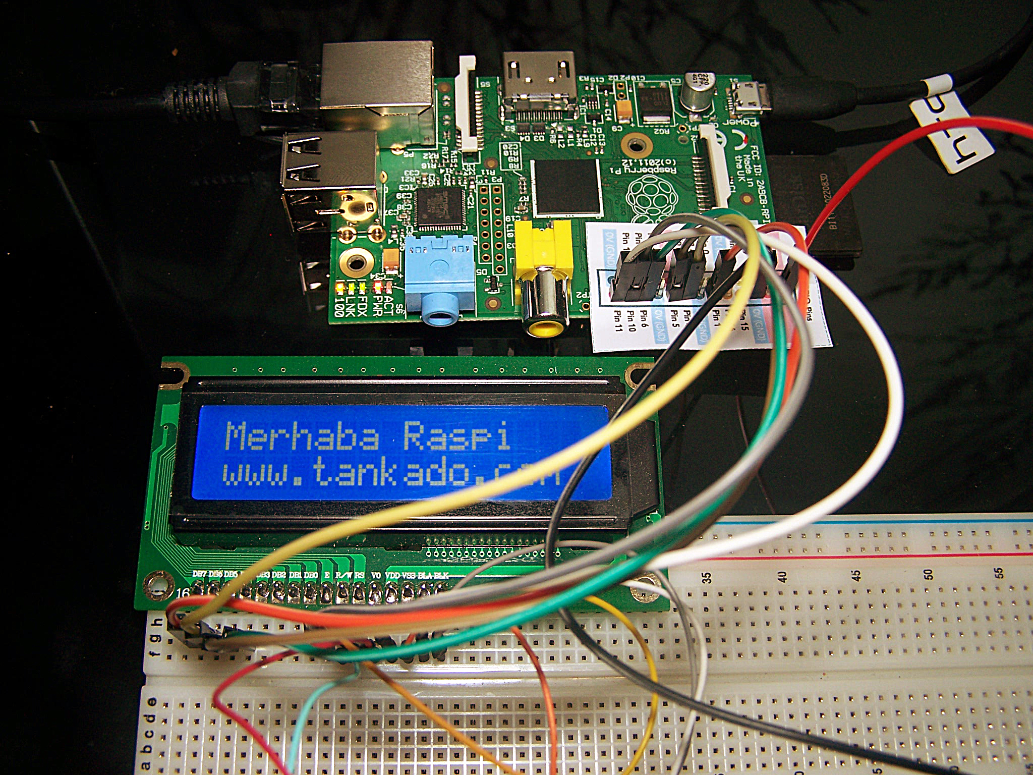
Tek tırnak işaretleri arasında verilen ilk parametre LCD ekranın birinci satırına, ikinci parametre de ikinci satırına yazdırılacak ve yazı ekranda kalacaktır.
|
1 2 3 4 5 6 7 8 9 10 11 12 13 14 15 16 17 18 19 20 21 22 23 24 25 26 27 28 29 30 31 32 33 34 35 36 37 38 39 40 41 42 43 44 45 46 47 48 49 50 51 52 53 54 55 56 57 58 59 60 61 62 63 64 65 66 67 68 69 70 71 72 73 74 75 76 77 78 79 80 81 82 83 84 85 86 87 88 89 90 91 92 93 94 95 96 97 98 99 100 101 102 103 104 105 106 107 108 109 110 111 112 113 114 115 116 117 118 119 120 121 122 123 124 125 126 127 128 129 130 131 132 133 134 135 136 137 138 139 140 141 142 143 144 145 146 147 148 149 150 151 |
#!/usr/bin/python # # HD44780 LCD Test Script for # Raspberry Pi # # Author : Matt Hawkins # Site : http://www.raspberrypi-spy.co.uk # # Date : 26/07/2012 # # Edited : Ozgur Koca # Site : http://raspberry-pi.tankado.com # Wiring-pi baglanti semasi # 1 : GND # 2 : 5V # 3 : Kontrast (0-5V)* (En yuksek parlaklik icin saseye bagla) # 4 : RS (Register Select) # 5 : R/W (Read Write) - Toprak # 6 : Enable or Strobe # 7 : Data Bit 0 - Kullanilmiyor # 8 : Data Bit 1 - Kullanilmiyor # 9 : Data Bit 2 - Kullanilmiyor # 10: Data Bit 3 - Kullanilmiyor # 11: Data Bit 4 # 12: Data Bit 5 # 13: Data Bit 6 # 14: Data Bit 7 # 15: LCD Arka aydinlatma +5V # 16: LCD ARka aydinlatma GND #import import RPi.GPIO as GPIO import time import sys # Define GPIO to LCD mapping LCD_RS = 7 LCD_E = 8 LCD_D4 = 25 LCD_D5 = 24 LCD_D6 = 23 LCD_D7 = 18 # Define some device constants LCD_WIDTH = 16 # Maximum characters per line LCD_CHR = True LCD_CMD = False LCD_LINE_1 = 0x80 # LCD RAM address for the 1st line LCD_LINE_2 = 0xC0 # LCD RAM address for the 2nd line # Timing constants E_PULSE = 0.00005 E_DELAY = 0.00005 def main(): # Main program block GPIO.setmode(GPIO.BCM) # Use BCM GPIO numbers GPIO.setup(LCD_E, GPIO.OUT) # E GPIO.setup(LCD_RS, GPIO.OUT) # RS GPIO.setup(LCD_D4, GPIO.OUT) # DB4 GPIO.setup(LCD_D5, GPIO.OUT) # DB5 GPIO.setup(LCD_D6, GPIO.OUT) # DB6 GPIO.setup(LCD_D7, GPIO.OUT) # DB7 # Initialise display lcd_init() # Send some test lcd_byte(LCD_LINE_1, LCD_CMD) lcd_string( str(sys.argv[1]) ) lcd_byte(LCD_LINE_2, LCD_CMD) lcd_string( str(sys.argv[2]) ) def lcd_init(): # Initialise display lcd_byte(0x33,LCD_CMD) lcd_byte(0x32,LCD_CMD) lcd_byte(0x28,LCD_CMD) lcd_byte(0x0C,LCD_CMD) lcd_byte(0x06,LCD_CMD) lcd_byte(0x01,LCD_CMD) def lcd_string(message): # Send string to display message = message.ljust(LCD_WIDTH," ") for i in range(LCD_WIDTH): lcd_byte(ord(message[i]),LCD_CHR) def lcd_byte(bits, mode): # Send byte to data pins # bits = data # mode = True for character # False for command GPIO.output(LCD_RS, mode) # RS # High bits GPIO.output(LCD_D4, False) GPIO.output(LCD_D5, False) GPIO.output(LCD_D6, False) GPIO.output(LCD_D7, False) if bits&0x10==0x10: GPIO.output(LCD_D4, True) if bits&0x20==0x20: GPIO.output(LCD_D5, True) if bits&0x40==0x40: GPIO.output(LCD_D6, True) if bits&0x80==0x80: GPIO.output(LCD_D7, True) # Toggle 'Enable' pin time.sleep(E_DELAY) GPIO.output(LCD_E, True) time.sleep(E_PULSE) GPIO.output(LCD_E, False) time.sleep(E_DELAY) # Low bits GPIO.output(LCD_D4, False) GPIO.output(LCD_D5, False) GPIO.output(LCD_D6, False) GPIO.output(LCD_D7, False) if bits&0x01==0x01: GPIO.output(LCD_D4, True) if bits&0x02==0x02: GPIO.output(LCD_D5, True) if bits&0x04==0x04: GPIO.output(LCD_D6, True) if bits&0x08==0x08: GPIO.output(LCD_D7, True) # Toggle 'Enable' pin time.sleep(E_DELAY) GPIO.output(LCD_E, True) time.sleep(E_PULSE) GPIO.output(LCD_E, False) time.sleep(E_DELAY) if __name__ == '__main__': main() |
LCD’yi 4bit’lik iletişim modunda kullandık ve Raspberry Pi ile 6 pin üzerinden (GPIO7-8-18-23-24-25) haberleştirdik. Kaynak kod içerisinde not olarak verilen Raspberry Pi bacakları WiringPi kütüphanesinde tanımlanmış olan bacak numaralarıdır. Bunların GPIO veya P1 karşılıklarını aşağıdaki tablodan görebilirsiniz.
| LCD Pin | Function | Pi Function | Pi Pin |
| 01 | GND | GND | P1-06 |
| 02 | +5V | +5V | P1-02 |
| 03 | Contrast | GND | P1-06 |
| 04 | RS | GPIO7 | P1-26 |
| 05 | RW | GND | P1-06 |
| 06 | E | GPIO8 | P1-24 |
| 07 | Data 0 | ||
| 08 | Data 1 | ||
| 09 | Data 2 | ||
| 10 | Data 3 | ||
| 11 | Data 4 | GPIO25 | P1-22 |
| 12 | Data 5 | GPIO24 | P1-18 |
| 13 | Data 6 | GPIO23 | P1-16 |
| 14 | Data 7 | GPIO18 | P1-12 |
| 15 | +5V via 560ohm | ||
| 16 | GND | P1-06 |